Feb 9, 2015 — These diagrams documented how connections between devices were made on relay panels; they are called “ladder” diagrams because they are .... Ladder diagram basically represents PLC circuits in much simpler way irrespective of the complexity of its control circuit. In order to create ladder diagrams, I have .... The ladder diagram consists of two vertical lines representing the power rails. Circuits are connected as horizontal lines, i.e., the rungs of the ...
Complete the following steps to add the diagram's rungs: Select Place»Place ladder rungs. The cursor appears with the rung's left and right terminators attached.. Ladder Diagram Definition ... A ladder diagram, shown in figure 3, is a diagram that explains the logic of the electrical circuit or system using standard NEMA or IEC ...
ladder diagram
ladder diagram, ladder diagram plc, ladder diagram examples, ladder diagram symbols, ladder diagram for logic gates, ladder diagram definition, ladder diagram programming, ladder diagram of and gate, ladder diagram software, ladder diagram maker, ladder diagram hvac, ladder diagram tutorial, ladder diagrams show Locas, 20200427_225700 @iMGSRC.RU
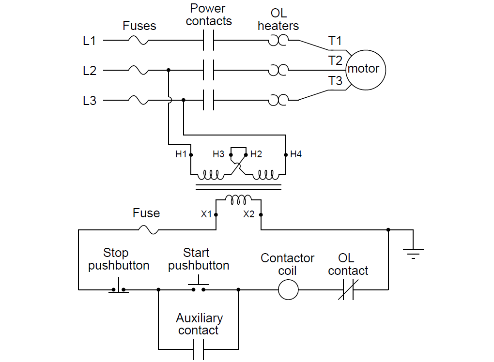
ladder diagram or electrical schematic or elementary diagram can be divided into two distinct portions. The first is the power portion and the second is the control .... Relay logic's ladder diagrams used physical contacts, coils, switches, and lots ... Early relay diagram symbols were literal interpretations of physical relay panels.. Aug 7, 2016 — Ladder diagrams are also called line diagrams or elementary diagrams. ... Connection diagrams or wiring diagrams shows the components of the ... Boleto Fast Completo Baixar Crackeado Torrent
ladder diagram examples

Ladder Diagram (LD). Definition: One of the IEC 61131-3 programming languages. Related Links. Ladder logic – Wikipedia · Ladder Logic Tutorial with Ladder .... What Is a Ladder Diagram? ... Ladder diagrams are advanced schematics widely used to record logic structures for industrial controls. These are called ladder ... Eerie, Indiana: The Other Dimension, Eerie (2) 17145 @iMGSRC.RU
ladder diagram for logic gates
Read about Ladder Diagram (LD) Programming (Basics of Programmable Logic Controllers (PLCs)) in our free Automation Textbook.. Feb 16, 2021 — A ladder diagram is the symbolic representation of the control logic used for ladder logic programming of a PLC. Ladder diagrams have .... Ladder diagram. A program is a series of instructions that directs the PLC to execute actions. Relay ladder logic, the standard programming language, is based .... Ladder logic has evolved into a programming language that represents a program by a graphical diagram based on the circuit diagrams of relay logic hardware.. Ladder diagram is a conventional form of programming the programmable logic controllers (PLCs). Ladder logic was originally developed as replacement for .... Aug 19, 2018 — What is the Ladder Diagram (LD)? ... The ladder diagram is the universal programming language of PLC. It has a short abbreviation as 'LD' and .... Ladder logic (also known as ladder diagram or LD) is a programming language used to program a PLC (Programmable Logic Controller). It is a .... Ladder Diagram is a graphical programming language that you use to develop software for programmable logic controllers (PLCs). It is one of the languages .... Nov 3, 2019 — Ladder diagram, better known as ladder logic, is a programming language used to program PLCs (programmable logic controllers). This article .... - [Instructor] Electrical schematics used to illustrate electric logic circuits are called ladder diagrams because on paper they resemble a ladder. The electric ... 88ba313fa9 Iain Armitage (Young Sheldon) (updated), Dfl6hVPW0AABCbG @iMGSRC.RU
